
Beginner guide: installing a MTB DP1 switch machine
Using servos as a switch machine was a mixed experience for me, leaving me slightly frustrated since I struggled to install them properly on some switches. Hence I gave the MTB DP1 switch machine a try in order to save me a headache. The DP1 comes with a built-in decoder that supports DCC, and takes care of the frog polarisation as well.
I consider myself a beginner to the hobby, since I’m still working on my very first layout. I decided to show how I installed the DP1 switch machine in case a fellow beginner is looking for a guide on how to install the machine. I’m using Tillig Elite Track switches, but the principle will work for other switches as well.
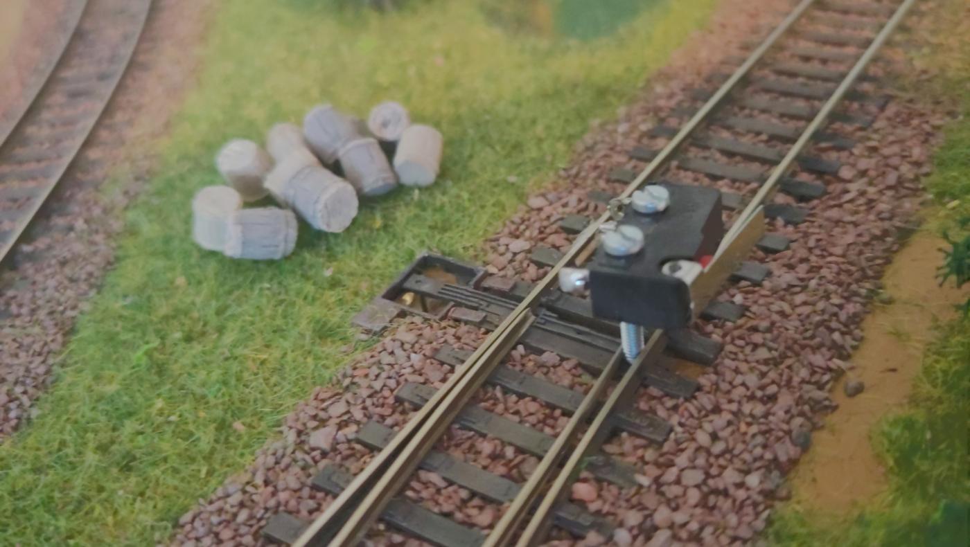
First put the switch in the end position of one side (thrown or closed) and fix it there with whatever you have lying around (like the screw of a micro switch in my case). This is necessary to know the switch machine’s end position (of one side).
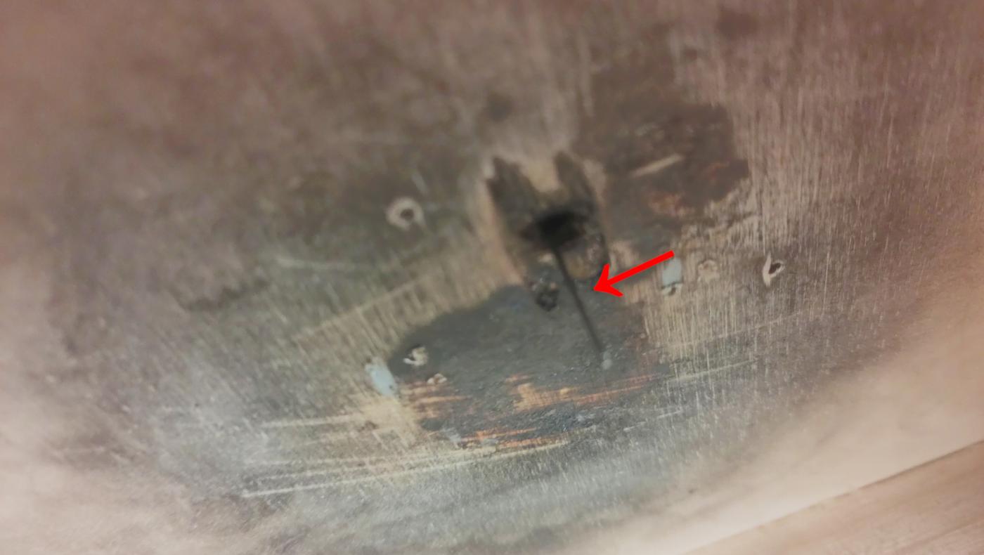
Sorry for the bad image quality, but it should be enough to illustrate the next step.
Then cut the setting wire to the necessary length, and insert it in the tip rod’s hole (or where applicable with your switch). The switch should hold it, while it “hangs” in the air, accessible under your layout. If the wire falls to the ground, you could fix it temporarily with some tape.
This is necessary to know where to place the switch machine.
Remove the front panel that will hold the setting wire by loosening the screw in the middle, and remove the front part entirely.
For the next step, keep all necessary tools close to you: the missing “hood” of the DP1 that fixates the setting wire, screws and screwdriver. Additionally, you might want to use a stitching awl before screwing in the screws under your layout.
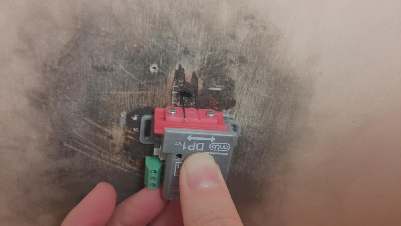
Now place the DP1 switching machine in position where the setting wire will be placed. Make sure that the DP1 will move in the right direction (towards the other end position of your switch—remember, we fixated the switch to be in one of the end positions, either thrown or closed).
Screw in two screws in the slit of the DP1 case. Be careful to tighten them hard enough so the switch machine won’t move around anymore, but not too tight for the case to be damaged.

You’re almost done. Screw the “hood” that holds the setting wire back on, and connect the DP1 to your DCC bus.
And now it’s time to test whether everything works. If necessary, you can move the whole “front panel” to fine-tune the position of the setting wire by removing both outer screws, move the front panel as much as you need, and tighten the screws again (see “Setting the needle longitudinal position” on the manufacturer’s website).